| View previous topic :: View next topic |
| Author |
Message |
emaxxenon
Joined: 21 Jan 2020
Posts: 42


|
| i2c Speed Setting |
 Posted: Wed Feb 26, 2020 8:36 am Posted: Wed Feb 26, 2020 8:36 am |
 |
|
Hi,
3 speeds are mentioned for i2c.
Standard
100 KHz / 5kΩ – 10kΩ
Fast Mode
400 KHz / 2kΩ – 5kΩ
High Fast Mode
3.4 MHz / 1kΩ
These are the resistors to be connected to hardware.
So what should I do in software?
I couldn't understand this topic. |
|
 |
temtronic
Joined: 01 Jul 2010
Posts: 9243
Location: Greensville,Ontario


|
|
 Posted: Wed Feb 26, 2020 8:59 am Posted: Wed Feb 26, 2020 8:59 am |
 |
|
We need to know which PIC and what I2C device you're using !! Add a 'link' to the 'device',either the chip or module. It's important as 'modules' tend to have 'other' parts on them, like pullup resistors or logic level conversions.
Jay
edit: I was first thinking the resistances were related to the speeds, bus loading ? BUT maybe some I2C 'device' or 'module' uses resistors to select the speed for that device, somewhat like USB devices have.....
Last edited by temtronic on Wed Feb 26, 2020 11:43 am; edited 1 time in total |
|
 |
PCM programmer
Joined: 06 Sep 2003
Posts: 21708


|
| Re: i2c Speed Setting |
 Posted: Wed Feb 26, 2020 11:07 am Posted: Wed Feb 26, 2020 11:07 am |
 |
|
| emaxxenon wrote: |
So what should I do in software?
|
Download the CCS manual.
http://www.ccsinfo.com/downloads/ccs_c_manual.pdf
Go to the #use i2c section. Look at these parameters for #use i2c():
| Quote: |
FAST - Use the fast I2C specification.
FAST=nnnnnn - Sets the speed to nnnnnn hz
SLOW - Use the slow I2C specification |
|
|
 |
emaxxenon
Joined: 21 Jan 2020
Posts: 42


|
|
 Posted: Wed Feb 26, 2020 11:38 pm Posted: Wed Feb 26, 2020 11:38 pm |
 |
|
| temtronic wrote: | We need to know which PIC and what I2C device you're using !! Add a 'link' to the 'device',either the chip or module. It's important as 'modules' tend to have 'other' parts on them, like pullup resistors or logic level conversions.
Jay
edit: I was first thinking the resistances were related to the speeds, bus loading ? BUT maybe some I2C 'device' or 'module' uses resistors to select the speed for that device, somewhat like USB devices have..... |
Thanks for your answer.
PIC18F25K22 - 20MHz oscillator.
I use SCL and SDA pins.
But what I want to know is whether I will add software for speed.
| PCM programmer wrote: | | emaxxenon wrote: |
So what should I do in software?
|
Download the CCS manual.
http://www.ccsinfo.com/downloads/ccs_c_manual.pdf
Go to the #use i2c section. Look at these parameters for #use i2c():
| Quote: |
FAST - Use the fast I2C specification.
FAST=nnnnnn - Sets the speed to nnnnnn hz
SLOW - Use the slow I2C specification |
|
Thank you. I really couldn't see this file.
I'm looking at.
Edit:
I work with 1 master and 16 slaves.
| Code: | | #use i2C (.................FAST=3400000) |
Will it run at 3.4mhz with this setting?
1kΩ -> Do I need to add this resistance?
and am I going to set this only to the master pic? |
|
 |
gjs_rsdi
Joined: 06 Feb 2006
Posts: 468
Location: Bali


|
|
 Posted: Thu Feb 27, 2020 12:05 am Posted: Thu Feb 27, 2020 12:05 am |
 |
|
Hi emaxxenon
I am using PIC18F26K22, same like you are using but with larger memory.
I am using:
| Code: | | #use I2C(MASTER, FAST=400000, I2C1, STREAM=I2CPORT)//I2C1 hardware used |
Never used faster than 400000.
You should think using higher speed for the PIC with FAST=3400000 in my opinion.
Regarding pull-up resistors. You need the resistors on the SCL and SDA line to the VDD. One resistor per line.
Take in consideration also that in I2C the lines between the Master and Slave have to be short. All the 16 slave will be on the same board as the Master?
Best wishes
Joe |
|
 |
Ttelmah
Joined: 11 Mar 2010
Posts: 19538


|
|
 Posted: Thu Feb 27, 2020 12:19 am Posted: Thu Feb 27, 2020 12:19 am |
 |
|
Going over 400KHz, requires active pull-ups, not just pull up resistors.
Look at the LTC1694 for a typical device.
Problem is that to have a low enough resistance to give fast rise times
takes more current than the I2C devices support driving.
The active pullups dynamically switch on the edges to give faster edges
without needing higher currents at the high/low states.
HS mode (never seen it called 'High Fast mode'), requires active pullups as
part of it's specification. |
|
 |
emaxxenon
Joined: 21 Jan 2020
Posts: 42


|
|
 Posted: Thu Feb 27, 2020 2:14 am Posted: Thu Feb 27, 2020 2:14 am |
 |
|
| gjs_rsdi wrote: | Hi emaxxenon
I am using PIC18F26K22, same like you are using but with larger memory.
I am using:
| Code: | | #use I2C(MASTER, FAST=400000, I2C1, STREAM=I2CPORT)//I2C1 hardware used |
Never used faster than 400000.
You should think using higher speed for the PIC with FAST=3400000 in my opinion.
Regarding pull-up resistors. You need the resistors on the SCL and SDA line to the VDD. One resistor per line.
Take in consideration also that in I2C the lines between the Master and Slave have to be short. All the 16 slave will be on the same board as the Master?
Best wishes
Joe |

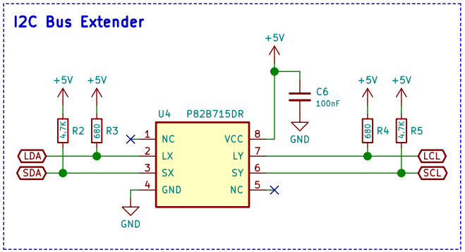
I am using P82b715.
16 slave pic will not be in the same place. I did my tests working.
The resistors I am using now are 4.7K.
I think it is used with 400Khz in this way.
| Code: | | #use I2C(MASTER, FAST=400000, ....) |
Am I going to set this only to the master pic?
Would it be a problem if I lower my resistance value and run it at higher speeds? |
|
 |
gjs_rsdi
Joined: 06 Feb 2006
Posts: 468
Location: Bali


|
|
 Posted: Thu Feb 27, 2020 2:58 am Posted: Thu Feb 27, 2020 2:58 am |
 |
|
Hi emaxxenon
For FAST=400000 I am using, 5V VDD I have 2K7 on both SCL and SDA.
It works perfect on the same board, a few centimeters distance.
The P82b715 is an I2C buffer for longer distance, still you will need pull-ups close to the PIC on ech side before the buffers in my opinion.
Page 9 Figure 4 don't show pull-ups but I think you still need them.
As Ttelmah wrote, at higher speeds you need the LTC1694 as active pull-ups.
The speed is set for the Master as he provides the clock to the slave. the slave will be like: | Code: | | #use i2c(Slave,Address=0xB0,I2C1)//I2C1 module, automatically hardware |
I use the address 0xB0 but you can chose any address as you wish, one for each slave.
Best wishes
Joe |
|
 |
emaxxenon
Joined: 21 Jan 2020
Posts: 42


|
|
 Posted: Thu Feb 27, 2020 3:10 am Posted: Thu Feb 27, 2020 3:10 am |
 |
|
| gjs_rsdi wrote: | Hi emaxxenon
For FAST=400000 I am using, 5V VDD I have 2K7 on both SCL and SDA.
It works perfect on the same board, a few centimeters distance.
The P82b715 is an I2C buffer for longer distance, still you will need pull-ups close to the PIC on ech side before the buffers in my opinion.
Page 9 Figure 4 don't show pull-ups but I think you still need them.
As Ttelmah wrote, at higher speeds you need the LTC1694 as active pull-ups.
The speed is set for the Master as he provides the clock to the slave. the slave will be like: | Code: | | #use i2c(Slave,Address=0xB0,I2C1)//I2C1 module, automatically hardware |
I use the address 0xB0 but you can chose any address as you wish, one for each slave.
Best wishes
Joe |
Hi, thanks for your answer.
The distance between the pic I use and p82b715 is close.
But the 4.7Ks are next to the p82b715.
I guess it doesn't cause much trouble.
A similar card is 2 meters away and communicates.
I can't add a new component to the circuit, but I can replace the 4.7K with a smaller resistor. But this is not a solution, as far as I understand.
 |
|
 |
Ttelmah
Joined: 11 Mar 2010
Posts: 19538


|
|
 Posted: Thu Feb 27, 2020 4:19 am Posted: Thu Feb 27, 2020 4:19 am |
 |
|
4K7 will only work at 400KHz, if the capacitance of the bus is very low (<50pF).
For a 100pF bus the maximum value is 2K5.
So 2K7 will handle perhaps 90pF OK.
I think the term you use is a result of confusing two different parts of the
I2C spec. There are four different I2C speed 'specs'.
Standard (up to 100Kb/sec)
Fast (up tp 400Kb/sec)
Fast plus (up to 1Mb/sec)
High speed (up to 3.4Mb/sec)
Fast plus can be done with resistive pull ups (though active is recommended)
High speed requires active pull ups.
For a 2m distance, you will run into capacitance problems unless you use
lower speeds or much more aggressive pull ups. |
|
 |
emaxxenon
Joined: 21 Jan 2020
Posts: 42


|
|
 Posted: Thu Feb 27, 2020 4:49 am Posted: Thu Feb 27, 2020 4:49 am |
 |
|
| Ttelmah wrote: | 4K7 will only work at 400KHz, if the capacitance of the bus is very low (<50pF).
For a 100pF bus the maximum value is 2K5.
So 2K7 will handle perhaps 90pF OK.
I think the term you use is a result of confusing two different parts of the
I2C spec. There are four different I2C speed 'specs'.
Standard (up to 100Kb/sec)
Fast (up tp 400Kb/sec)
Fast plus (up to 1Mb/sec)
High speed (up to 3.4Mb/sec)
Fast plus can be done with resistive pull ups (though active is recommended)
High speed requires active pull ups.
For a 2m distance, you will run into capacitance problems unless you use
lower speeds or much more aggressive pull ups. |
I will consider your suggestions.
Will the P82B715 I use for communication not provide this?

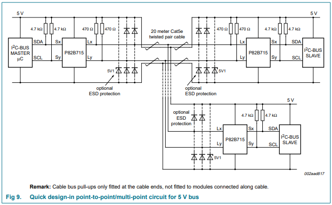
https://www.nxp.com/docs/en/data-sheet/P82B715.pdf
I adjusted it according to this scheme.
Should I change the resistance value to <2K5 ? |
|
 |
Ttelmah
Joined: 11 Mar 2010
Posts: 19538


|
|
 Posted: Thu Feb 27, 2020 5:06 am Posted: Thu Feb 27, 2020 5:06 am |
 |
|
On what you show here the pull ups on the long part of the I2C bus are only
470R. This is a much more capable value for this.
However you need to look at what the quoted capacitance of the
wire is, and then add all the capacitances of all the connected transceivers.
Assuming this is OK.
Then the only problem will be if the capacitance of the short sections between
the transceivers and the devices are too much. The chip pins themselves
will give something like 5pF at each end of the section. Even a couple of
inches of track will probably have perhaps 10pF capacitance, so the 4K7's
don't give a lot of margin.
Remember also capacitances can start to shoot up if the units get damp.... |
|
 |
emaxxenon
Joined: 21 Jan 2020
Posts: 42


|
|
 Posted: Thu Feb 27, 2020 5:24 am Posted: Thu Feb 27, 2020 5:24 am |
 |
|
| Ttelmah wrote: | On what you show here the pull ups on the long part of the I2C bus are only
470R. This is a much more capable value for this.
However you need to look at what the quoted capacitance of the
wire is, and then add all the capacitances of all the connected transceivers.
Assuming this is OK.
Then the only problem will be if the capacitance of the short sections between
the transceivers and the devices are too much. The chip pins themselves
will give something like 5pF at each end of the section. Even a couple of
inches of track will probably have perhaps 10pF capacitance, so the 4K7's
don't give a lot of margin.
Remember also capacitances can start to shoot up if the units get damp.... |
Thank you for the information. |
|
 |
temtronic
Joined: 01 Jul 2010
Posts: 9243
Location: Greensville,Ontario


|
|
 Posted: Thu Feb 27, 2020 5:27 am Posted: Thu Feb 27, 2020 5:27 am |
 |
|
I have to ask do you really NEED the very,very high speed ? Do you have a LOT of data that must be transferred all the time, or just a few bytes? Is the data from say sensors(on/off switches) or remote ADC units ? What is the physical layout of the 'slaves'( how close ? on same PCB ??)
Can you split the 16 slaves into 2 or 4 groups ?
I2C may not be the ideal or best choice for the communications. |
|
 |
emaxxenon
Joined: 21 Jan 2020
Posts: 42


|
|
 Posted: Thu Feb 27, 2020 6:13 am Posted: Thu Feb 27, 2020 6:13 am |
 |
|
| temtronic wrote: | I have to ask do you really NEED the very,very high speed ? Do you have a LOT of data that must be transferred all the time, or just a few bytes? Is the data from say sensors(on/off switches) or remote ADC units ? What is the physical layout of the 'slaves'( how close ? on same PCB ??)
Can you split the 16 slaves into 2 or 4 groups ?
I2C may not be the ideal or best choice for the communications. |
I don't need a very, very high speed.
But if there is a possibility, I would like to try it.
| Code: |
//CARD1
for(int i=0; i<16; i++)
{
//Receiver IR
i2c_start();
i2c_write(R_SLAVE1_W);
i2c_write(i);
i2c_stop();
//Transmitter IR
i2c_start();
i2c_write(T_SLAVE1_W);
i2c_write(i);
i2c_stop();
delay_us(10);
}
i2c_start();
i2c_write(R_SLAVE1_R);
R1_1 = i2c_read();
R1_2 = i2c_read(0);
i2c_stop();
//CARD2
for(int i=0; i<16; i++)
{
//Receiver IR
i2c_start();
i2c_write(R_SLAVE2_W);
i2c_write(i);
i2c_stop();
//Transmitter IR
i2c_start();
i2c_write(T_SLAVE2_W);
i2c_write(i);
i2c_stop();
delay_us(10);
}
i2c_start();
i2c_write(R_SLAVE2_R);
R2_1 = i2c_read();
R2_2 = i2c_read(0);
i2c_stop();
//CARD3
.
.
.
|
I have such a literacy process.

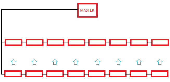
There are 16 slaves. 8 receiver IR - 8 transmitter IR cards.
There are 16 IR leds on each card. Toplamda 2x128 adet led bulunur.
I scan them by opening and closing them respectively.
1.CARD -> Receiver & Transmitter 1.IR on...off, 2.IR on...off, .... 16.IR on...off
1.CARD send to Master "1.Card 16 IR LED status"
2.CARD -> Receiver & Transmitter 1.IR on...off, 2.IR on...off, .... 16.IR on...off
2.CARD send to Master "2.Card 16 IR LED status"
...
The master only tells you which led to burn.
And it learns the status of IR led from the receiver.
I have to use I2C because the circuit is prepared.
The change I can make is resistance values or minor software changes. |
|
 |
|


