 |
 |
| View previous topic :: View next topic |
| Author |
Message |
PIC457
Joined: 01 Jan 2012
Posts: 3


|
| priority interrupts in PIC16F877A |
 Posted: Sun Jan 01, 2012 4:06 pm Posted: Sun Jan 01, 2012 4:06 pm |
 |
|
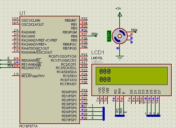
Hi everybody ! I'm making a project about DC servo (count Pulse encode)... and I have met with difficulties. I do not know what is happening. It took me a long time ... But in the end I did not solve the problem....
This in my code:
| Code: |
#include <16F877A.h>
#include <DEF_877A.h>
#device *=16 adc=10
#FUSES NOWDT, HS, NOPUT, NOPROTECT, NOLVP
#use delay(clock=20000000)
//#define LCD_DATA_PORT getenv("SFR:PORTD")
#define LCD_ENABLE_PIN PIN_E0 ////
#define LCD_RS_PIN PIN_E1 ////
#define LCD_RW_PIN PIN_E2
#define LCD_DATA4 PIN_D4 ////
#define LCD_DATA5 PIN_D5 ////
#define LCD_DATA6 PIN_D6 ////
#define LCD_DATA7 PIN_D7
#include <lcd.c>
int16 h=0,chuc,tram,h1,donvi,k=0;
int16 count=0;
#int_RB
void int_RB()
{
disable_interrupts(int_rb);
disable_interrupts(int_timer0);
GIE =1;
if(RBIF)
{
if(RB0==1||RB0==0) // check L_To_H and H_To_L
h++; // count
RBIF=0;
}
}
#int_timer0
void int_timer0()
{
disable_interrupts(int_timer0);
GIE =1;
if(tmr0if)
{
++count;
if(count==5000) // period display LCD
{
count=0;
h1=h;
k = h1+10;
h=0; // reset count
set_timer0(6);
tmr0if=0;
}
}
}
void main()
{
set_tris_b(0b11110001);
lcd_init();
delay_ms(100);
enable_interrupts(int_timer0);
setup_timer_0(RTCC_INTERNAL|RTCC_DIV_2);
set_timer0(6);// T_dt = 2*(256 - 6)*1us = 500us
enable_interrupts(int_rb);
ext_int_edge(L_to_H);
enable_interrupts(global);
while(1)
{
tram =h1/100;
h1=h1%100;
chuc=h1/10;
donvi=h1%10;
lcd_gotoxy(1,1);
LCD_Putc(tram+0x30);
LCD_Putc(chuc+0x30);
LCD_Putc(donvi+0x30);
tram =k/100;
k=k%100;
chuc=k/10;
donvi=k%10;
lcd_gotoxy(1,2);
LCD_Putc(tram+0x30);
LCD_Putc(chuc+0x30);
LCD_Putc(donvi+0x30);
}
}
|
And Result :

Hope the help from everyone !!! |
|
 |
temtronic
Joined: 01 Jul 2010
Posts: 9260
Location: Greensville,Ontario


|
|
 Posted: Sun Jan 01, 2012 4:54 pm Posted: Sun Jan 01, 2012 4:54 pm |
 |
|
quick comments...
1) you do not have to disable/enable interrupts inside ISRs, compiler takes care of that.
2) you do not have to use the set_tris......() functions, again the compiler does that
3) with respect to the schematic, there are lots of errors and if wired as such will never work. Pins like osc pins, Vdd,Vss,_mclr, Vee of LCD.
4) If the 'device' attached to RB4 is a 'servo', do we assume it's a hobby type RC servo ? If so, it'll never work as +3V is NOT the normal voltage they require.
OR is the 'device' really a mechanical quadrature encoder? In that case, it'll never work as again +3V is applied to it, yet the PIC requires +5V for correct operation.Also no pin use is shown....
As for the code, you need to add comments on every line( they're free - don't take up space) to describe WHAT you're trying to do...not to many people here will try to figure out uncommented code. A brief description at the beginning would help as the schematic isn't complete.
The more information you supplied the better and faster we can help.Saying 'doesn't work' means nothing as we don't know what is supposed to happen.
this is a start...... |
|
 |
PIC457
Joined: 01 Jan 2012
Posts: 3


|
|
 Posted: Sun Jan 01, 2012 6:43 pm Posted: Sun Jan 01, 2012 6:43 pm |
 |
|
Thanks temtronic ! Thanks you very much !!!
I've revised my code as yours guide .... and now it is good ... but I have a question that In PIC16F is only interrupts vector ... In case 2 interrupts coincides .... then what happens ??? And how to fix ????
| Code: |
#int_RB // interrupts RB4-RB7
{
if((RBIF)&&(RBIE)) // Bit interrupts flag RB and Bit interrupts enable RB
{
//code here
RBIF=0; // Clear bit RBIF
}
}
#int_timer0 // interrupts timer0
{
if(tmr0if) // Bit interrupts flag timer 0
{
// code here
tmr0if=0; // clear bit flag
}
}
|
|
|
 |
Ttelmah
Joined: 11 Mar 2010
Posts: 19578


|
|
 Posted: Mon Jan 02, 2012 2:51 am Posted: Mon Jan 02, 2012 2:51 am |
 |
|
Basically nothing......
The hardware only supports one interrupt 'level'. In CCS, the interrupt defined _first_, or the one listed first in a 'priority' statement, is always checked first. This is the interrupt 'priority' for a 16 family Chip. Remember the interrupt flag, once set, remains set till the handler is called, so what will happen is that if two interrupts trigger together, the one with the highest priority gets serviced first, and then the lower priority one is called.
On your code, you don't need to touch the interrupt flag, or check it. This is all already done for you. The 'RB' interrupt code will _only_ be called, if RBIF is set, and RBIE is set. Checking it again, is a waste of time. The compiler also automatically clears the interrupt flag when you leave the routine. Key thing in INT_RB, is that you _must_ read the port. The RBIF bit _cannot_ be cleared, until the port is read. It'll reset itself on the very next instruction, and 'INT_RB' will execute for ever.
Similarly on the timer code, tmr0if, _is_ set if the code is called, and will be cleared automatically when you leave the routine.
Critical thing throughout, is get out of the handlers quickly. Since the next interrupt won't be handled until you leave the handler code.
Best Wishes |
|
 |
PIC457
Joined: 01 Jan 2012
Posts: 3


|
|
 Posted: Mon Jan 02, 2012 9:26 am Posted: Mon Jan 02, 2012 9:26 am |
 |
|
Thank you for the useful advice !!!    |
|
 |
|
|
You cannot post new topics in this forum
You cannot reply to topics in this forum
You cannot edit your posts in this forum
You cannot delete your posts in this forum
You cannot vote in polls in this forum
|
Powered by phpBB © 2001, 2005 phpBB Group
|


