 |
 |
| View previous topic :: View next topic |
| Author |
Message |
viki2000
Joined: 08 May 2013
Posts: 233


|
| How to increase the SPI speed? |
 Posted: Mon Jan 30, 2017 9:44 am Posted: Mon Jan 30, 2017 9:44 am |
 |
|
I use MCP4921 SPI DAC to generate a rectified sine wave 1Vpp 100Hz.
Starting from next Code Library:
http://www.ccsinfo.com/forum/viewtopic.php?t=53205&highlight=mcp4921
I customized it for PIC18F4550 to generate a rectified sine-wave.
I was inspired by next webpage, but I wanted to test it with CCS C compiler:
http://pic-tutorials.blogspot.de/
The PIC18F4550 works with an external crystal 20MHz and with PLL heaving then the clock 48MHz.
This is my schematic:
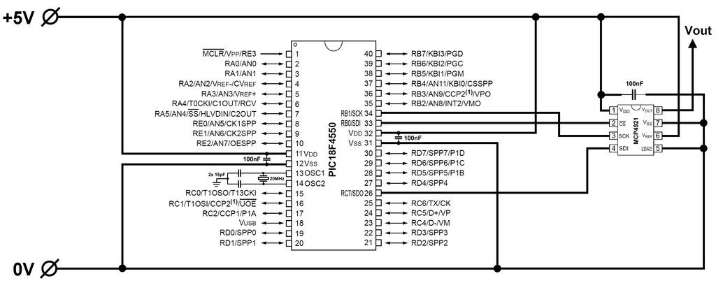
And this is code:
| Code: | #include <18F4550.h>
#use delay(clock=48000000,crystal=20000000,restart_wdt)
//#define SPI_MODE_0 (SPI_L_TO_H | SPI_XMIT_L_TO_H)
#define CLK PIN_B1
#define CS PIN_B0
#define SDI PIN_C7
void init_dac();
void DAC_write(unsigned char cmd, unsigned long data);
CONST unsigned long SINE_WAVE[250] = {0, 10, 21, 31, 41, 51, 62, 72, 82, 92, 103, 113, 123, 133, 143, 153, 164, 174, 184, 194, 204, 214, 224, 233, 243, 253, 263, 273, 282, 292, 301, 311, 321, 330, 339, 349, 358, 367, 376, 386, 395, 404, 412, 421, 430, 439, 447, 456, 465, 473, 481, 490, 498, 506, 514, 522, 530, 538, 545, 553, 561, 568, 575, 583, 590, 597, 604, 611, 618, 624, 631, 638, 644, 650, 656, 663, 669, 674, 680, 686, 692, 697, 702, 708, 713, 718, 723, 727, 732, 737, 741, 745, 750, 754, 758, 761, 765, 769, 772, 776, 779, 782, 785, 788, 791, 793, 796, 798, 800, 803, 804, 806, 808, 810, 811, 813, 814, 815, 816, 817, 817, 818, 818, 819, 819, 819, 819, 819, 818, 818, 817, 817, 816, 815, 814, 813, 811, 810, 808, 806, 804, 803, 800, 798, 796, 793, 791, 788, 785, 782, 779, 776, 772, 769, 765, 761, 758, 754, 750, 745, 741, 737, 732, 727, 723, 718, 713, 708, 702, 697, 692, 686, 680, 674, 669, 663, 656, 650, 644, 638, 631, 624, 618, 611, 604, 597, 590, 583, 575, 568, 561, 553, 545, 538, 530, 522, 514, 506, 498, 490, 481, 473, 465, 456, 447, 439, 430, 421, 412, 404, 395, 386, 376, 367, 358, 349, 339, 330, 321, 311, 301, 292, 282, 273, 263, 253, 243, 233, 224, 214, 204, 194, 184, 174, 164, 153, 143, 133, 123, 113, 103, 92, 82, 72, 62, 51, 41, 31, 21, 10};
void main(){
setup_adc(ADC_OFF);
//setup_spi(SPI_MASTER | SPI_MODE_0 | SPI_CLK_DIV_4);
unsigned long int i=0;
while(TRUE){
if (i++ == 249)
i = 0;
DAC_write(0x30, SINE_WAVE[i]);
}
}
void init_dac()
{
output_high(CS);
output_high(CLK);
output_high(SDI);
}
void DAC_write(unsigned char cmd, unsigned long data)
{
unsigned char s = 16;
unsigned long value = 0;
value = cmd;
value <<= 8;
value |= (data & 0xFFF);
output_low(CS);
while(s > 0)
{
if((value & 0x8000) != 0)
{
output_high(SDI);
}
else
{
output_low(SDI);
}
output_low(CLK);
output_high(CLK);
value <<= 1;
s -= 1;
}
output_high(CS);
//delay_us(10);
} |
As you may see above, I use lookup table with 250 values to generate 1Vpp 100Hz rectified sine-wave.
The values are generated with the software SMART SINE from here:
http://tahmidmc.blogspot.de/2012/10/smart-sine-software-to-generate-sine.html
That is already far better than only 100 values lookup table with I2C here:
http://www.ccsinfo.com/forum/viewtopic.php?p=209877#209877
The oscilloscope screenshots with MCP4921 SPI DAC are here:
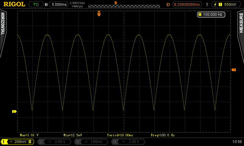
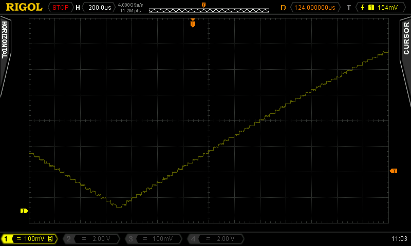
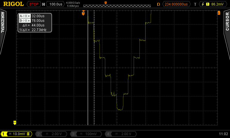
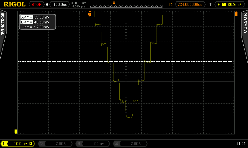
When I measure the SPI clock signal with the oscilloscope, then I see 500KHz.
I would like to increase that clock to higher values and to enlarge the lookup table.
Of course another solution would be a trigonometric function, which I may consider later for comparison.
How do you setup/increase the SPI bus clock/frequency? |
|
 |
temtronic
Joined: 01 Jul 2010
Posts: 9244
Location: Greensville,Ontario


|
|
 Posted: Mon Jan 30, 2017 9:53 am Posted: Mon Jan 30, 2017 9:53 am |
 |
|
simple answer is to read the CCS manual, #use spi().......
kinda funny how stuff like this is in there....
BTW pressing F11 while your project is open, actually opens up the manual.
I'm pretty sure without a 'baud=xxxx' entry in SPI(....), CCS will default to as fast as possible.
Others can confirm/deny as this PC isn't my eng PC.
Jay |
|
 |
Ttelmah
Joined: 11 Mar 2010
Posts: 19545


|
|
 Posted: Mon Jan 30, 2017 10:17 am Posted: Mon Jan 30, 2017 10:17 am |
 |
|
The code you are pointing to, uses software SPI.
Don't. Use the hardware instead.
Connect the CS to a different pin. SDI, is the spi data input for the hardware, You need to be using a pin that is not part of the hardware for the CS.
Assuming B2 below (change to suit what you can do).
#USE SPI, and spi_xfer.
Use this.
#USE SPI(SPI1, mode=0, bits=16, enable=PIN_B2, STREAM=MCP4921)
Then:
spi_xfer(MCP4921, val);
where 'val' is an int16, will clock the data out at 12Mb/sec....
The dac_write in the code you point to, becomes:
| Code: |
void DAC_write(unsigned char cmd, unsigned long data)
{
int16 value;
value = cmd;
value <<= 8;
value |= (data & 0xFFF);
spi_xfer(MCP4921, value);
}
|
Honestly, save time, and make the #defines for the commands be the 16bit values. So (for instance):
#define BUFFER_ON 0x4000
etc..
Then you can get rid of the rotations, as:
| Code: |
void DAC_write(unsigned int16 command, unsigned int16 data)
{
spi_xfer(MCP4921,data | command);
}
|
|
|
 |
viki2000
Joined: 08 May 2013
Posts: 233


|
|
 Posted: Mon Jan 30, 2017 11:51 am Posted: Mon Jan 30, 2017 11:51 am |
 |
|
Thank you for suggestions.
I will check them during next days. |
|
 |
|
|
You cannot post new topics in this forum
You cannot reply to topics in this forum
You cannot edit your posts in this forum
You cannot delete your posts in this forum
You cannot vote in polls in this forum
|
Powered by phpBB © 2001, 2005 phpBB Group
|


